ZIA TM4C123G Board Simulator

A complete TM4C123G lab board that runs on the student’s own PC. It runs the same program files Keil uVision 5 builds, so the lab continues at home, in the library or in a lecture.
Open for university pilots
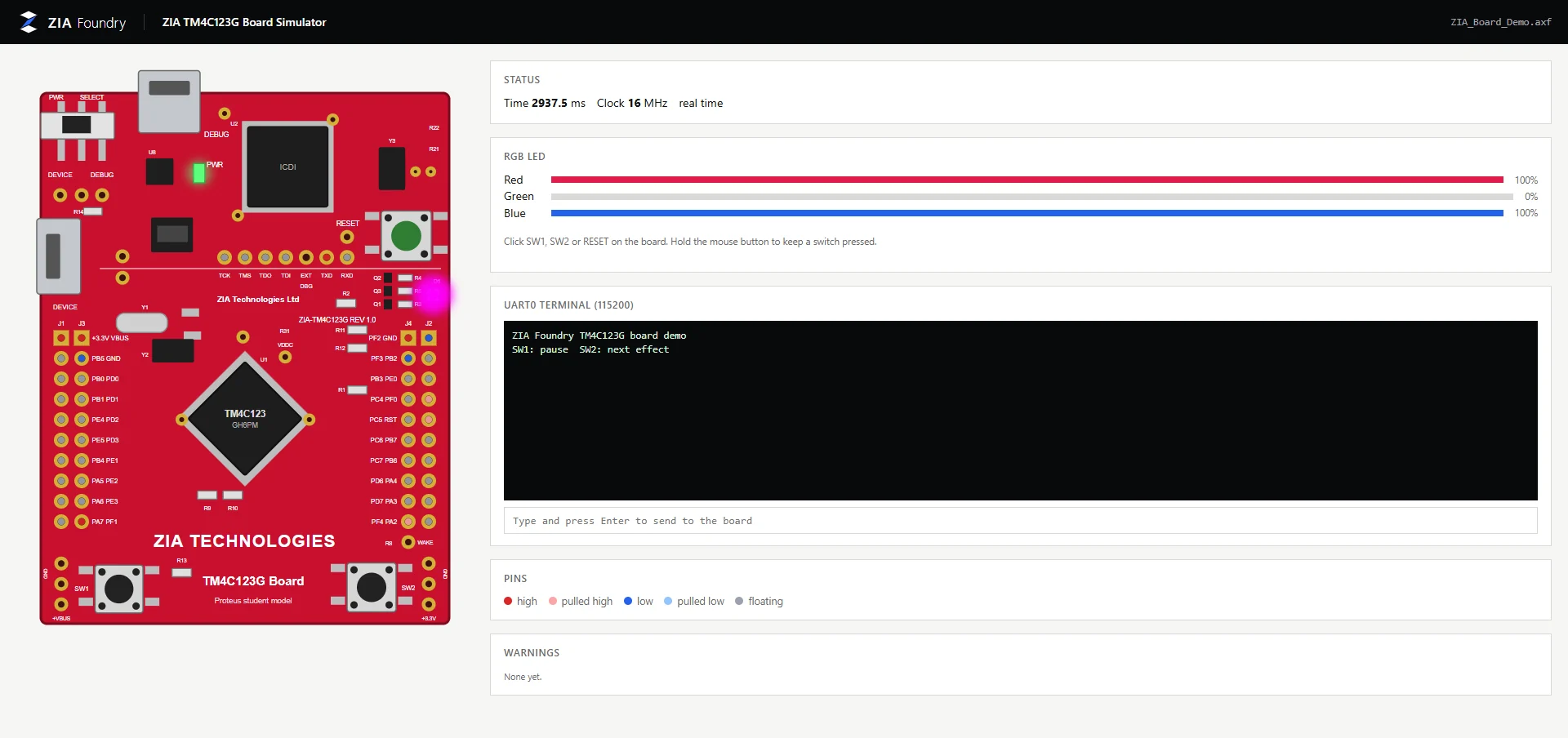
ZIA Board Viewer running a demo program: the board with its RGB LED lit, LED levels, a UART0 terminal and pin states

The ZIA Board Viewer running the demo program. This is a real screenshot.

How it works

From build to board in three steps.

No new tools to learn. The simulator sits behind the Keil project students already have.

  1. 01

    Build in Keil uVision 5

    Students write and build their project the usual way. Nothing in the code changes for the simulator.

  2. 02

    Click Tools, then Run on ZIA Board

    One menu item in Keil sends the built program to the simulated board.

  3. 03

    The board runs in the browser

    The ZIA Board Viewer opens at a local address and runs the program in real time.

What students see

The board, as it behaves on the bench.

01

Live RGB LED

The LED glows in the colour and brightness the program drives, including PWM dimming.

02

Clickable switches

SW1, SW2 and RESET are pressed with the mouse. Hold the button to keep a switch pressed.

03

UART0 terminal

Text the program sends appears in a terminal, and typed input goes back to the board.

04

Plain-language warnings

Common mistakes are explained in words, for example: “Port F was used before its clock was turned on”.

05

Live pin states

Every header pin shows whether it is high, low, pulled or floating while the program runs.

06

Virtual parts on the buses

An I2C EEPROM, an I2C temperature sensor and an SPI serial RAM can be connected for bus labs.
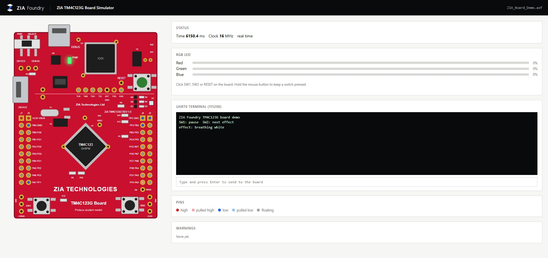
ZIA Board Viewer after SW2 is pressed: the LED effect has changed and the terminal reports the switch press

After pressing SW2 with the mouse, the program changes the LED effect.

Architecture

One program. The same board, everywhere.

The student builds once in Keil. The same file runs on the real board, in the browser and, soon, inside Proteus.

04

Front ends

Where the student sees and touches the board.

  • ZIA Board Viewer, in the browser
  • Proteus model, in development
03

ZIA simulator core

The microcontroller and the parts around it, modelled register by register.

  • GPIO A to F
  • UART0 to 7
  • Timers
  • ADC0, ADC1
  • PWM0, PWM1
  • I2C0 to 3
  • SSI0 to 3
02

Processor

A Cortex-M4F core with FPU, interrupts, SysTick, clock and PLL.

  • Cortex-M4F
  • NVIC
  • SysTick
01

The student’s program

The .axf file Keil uVision 5 builds, with no changes for the simulator.

  • Keil uVision 5 project
46
board pins modelled, in the positions of the real board
8
UART channels, with UART0 in a live terminal
12
general purpose timers, 16/32-bit and wide
4
independent references every release is tested against

Coverage

What is simulated.

The parts of the microcontroller that teaching labs use, modelled at register level.

Processor
Cortex-M4F core with FPU, NVIC and SysTick
System
System control, clock and PLL
GPIO
Ports A to F
UART
UART0 to UART7. UART0 appears in the terminal, like the virtual COM port of the real board
Timers
TIMER0 to TIMER5 and WTIMER0 to WTIMER5: periodic, one-shot, count up and down, prescaler, PWM, edge count and edge time capture
ADC
ADC0 and ADC1, all four sequencers, AIN0 to AIN11, temperature sensor, averaging, processor, timer, PWM and always triggers
PWM
PWM0 and PWM1 with four generators each, count-down and up/down modes, deadband, interrupts and ADC triggers
I2C
I2C0 to I2C3 in master mode
SSI
SSI0 to SSI3 in master mode
On the board
RGB LED with brightness, SW1, SW2, RESET and the R9 / R10 links
Virtual parts
24C02 I2C EEPROM, LM75 I2C temperature sensor and an SPI serial RAM can be placed on the buses

Not simulated yet

We say what is missing.

Programs that use these parts still run. Those registers read as 0 and the simulator prints a warning, so nobody is left guessing.

  • PWM fault inputs
  • I2C and SSI slave mode
  • I2C loopback
  • ADC digital comparators
  • QEI
  • CAN
  • USB
  • Hibernation
  • EEPROM
  • Watchdog
  • Timer RTC mode
  • uDMA
  • TivaWare ROM functions

Verification

Tested against four independent references.

A simulator used for teaching has to give the same answer as the real board. We check that from four directions, and we plant bugs on purpose to prove the tests catch mistakes.

  1. 01The student lab programs and their known answers
  2. 02An independent open source emulator, compared instruction by instruction
  3. 03Results computed separately in Python
  4. 04The reset values in the microcontroller data sheet

At a glance

Specifications.

Program files
The .axf files built by Keil uVision 5
Runs on
The student’s Windows PC. The board opens in the web browser at a local address
Speed
About 1.1 to 3.5 times real time at 16 MHz, depending on the program
Board
Compatible with the EK-TM4C123GXL pin-out
Licence
University site licence, per semester or per year

Try it with your own lab programs.

We are opening pilots with engineering departments. Send us a lab sheet and we will show it running.